Discussion
1. Introduction
The object of this project was to form DNA Origami structures based on Miura Folding to realize DNA nanostructures with controllable transformability. In order to control the transformation of our DNA origami units, we introduced a mechanism, “Miura Folding”, to keep the structure in Open and Closed states selectively. Here, the Bridge and the Latch DNA strands were applied to our units to control the transition between Open and Closed states, and we further tried to simplify the transformation mechanism by combining both DNAs into one, as shown in videos as follows.
Video 1. Unity Simulation for Open to Closed
Video 2. Unity Simulation for Closed to Open
These videos are animations made using the Game Engine Unity, where models were based on the DNA nanostructures of our design. As seen in these animations, if we could control the opening and closing of the Miura Folding structure according to multiple signal strands, by combining multiple types of Miura Folding Units having different strands as their signals, we can realize DNA Nanostructures performing more complex transformations. Here we examined the possibility of realizing an integrated system which enables controlled transformation of DNA nanostructures by a single type of DNA strand.
2. Design
In addition to the main experiments using the design shown in Fig.4 of Design page, we also experimented using a separately design shown in figure below.
_1500-763.png)
Fig.1 Schematic for additional experiment
In our previous design, both Bridge and Latch were used to assure that the structure fully took its Closed and Open states upon transformation. However, for this design here, since the main objective was to perform dynamic open/close movements, a mechanism was designed so that structure transformation would occur by only single-stranded signal reactions using Bridge. In the following, Bridge will be termed as Actuator, reflecting its main role in the design.
In the initial state, Close forms double strands with Actuator, pulling the DNA Origami panels closer together to maintain the Closed structure. Next, upon the addition of Signal, Close is displaced and Signal and Actuator form rigid double strands from toehold c of actuator to open the DNA Origami panels. Furthermore, when Anti-Signal, which is complementary to Signal, is added, Signal is released from Actuator and becomes waste products with Anti-signal. Since Close remaining in the solution will have single-stranded sequences, it can react with Actuator to form double-strands, once again closing the structure. Thus, the Miura Folding Unit can be opened and closed repeatedly by strand displacement reactions only using single-stranded DNA signals and Actuator.
3. Experiments
For our experiments, first we examined the designed DNA strands using gel electrophoresis, in order to confirm the strand displacement reactions as well as obtain the optimum concentration conditions for Signal and Anti-Signal. Next, we examined the strand reactions with DNA Origami panels by using gel electrophoresis and AFM to confirm proper formation of the designed Miura Folding units. Results and discussions are shown in the following.
Strand Mechanism and Concentration Condition Experiments
3.1 Signal
Purpose
To determine the optimal concentration of Signal which will effectively displace Close and form double strands with Actuator to hold open the structure, samples of different Signal concentrations were examined by gel electrophoresis.
Results and Discussion
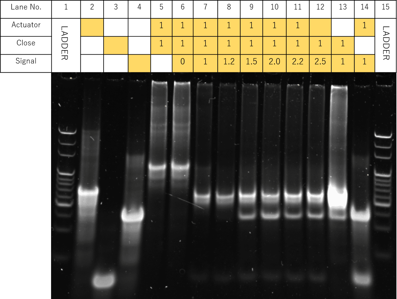
Fig.2 Electrophoresis of concentration-gradient of signal DNA
The results of the electrophoresis are shown in Fig. 2. Samples with Actuator, Close, and Signal were prepared according the table, where the Signal concentrations of Lanes 6-12 were each adjusted to be 0, 1, 1.2, 1.5, 2.0, 2.2, 2.5 times that of Actuator and Close.
In Lanes 7 to 12, a specific band only seen in Lane 12, thought to represent the hybridized Actuator and Signal was shown, suggesting the successful opening of the panels. Likewise, for Lanes 7 to 12, a band seen in Lane 13, thought represent the hybridized Close and Signal was also observed. In particular, for Lane 8, the band representing double-strands of Actuator and Closed seen in Lane 5 was not observed, while a slight band similar to that of Lane 3, thought to represent Close, was observed.
Since the results suggest that in Lane 8, the Open State was formed most successfully according to our design, we decided to perform our experiments under Signal concentration ratio of Actuator:Close:Signal=1:1:1.2.
3.2 Anti-Signal
Purpose
To determine the optimal concentration of Anti-Signal which will effectively form double strands with Signal , we prepared samples of different Anti-signal concentrations and performed gel electrophoresis.
Results and Discussion
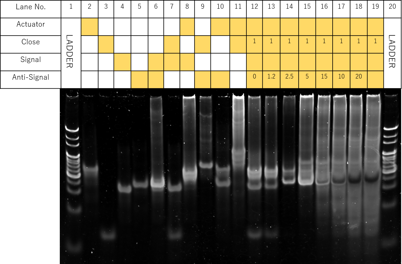
Fig.3 Electrophoresis of concentration-gradient of Anti-signal DNA
The results of the electrophoresis are shown in Fig. . Samples with Actuator, Close, Signal, and Anti-Signal were prepared according the table, where in Lanes 12-19, concentration ratios of Actuator:Close:Signal were kept at 1:1:1.2, while Anti-signal concentrations were each adjusted from 0 to 4.5 times that of Actuator.
(Note: For Lane 8, no bands were observed due to misapplication during sample preparations)
However, it must be noted that for Lanes 13-19, a clear unexpected band likewise to Lane 9 was also observed, suggesting unexpected reactions between Close and Anti-Signal. Furthermore, bands similar to Lane 12, representing hybridizations between Actuator and Signal were shown to remain. In Lanes 14-19, a band similar to Lane 2, representing monomers of Actuator was also seen. This suggests incomplete strand displacement reactions. In addition, smears of multimers of larger molecular weights were seen throughout all lanes.
These unexpected structures and multimers can be hypothesized to be formed mainly due to unexpected reactions between Close and Anti-Signal. Since Anti-Signal reacts with Close before it does with Signal, it becomes difficult for Actuator to form double strands with Close.
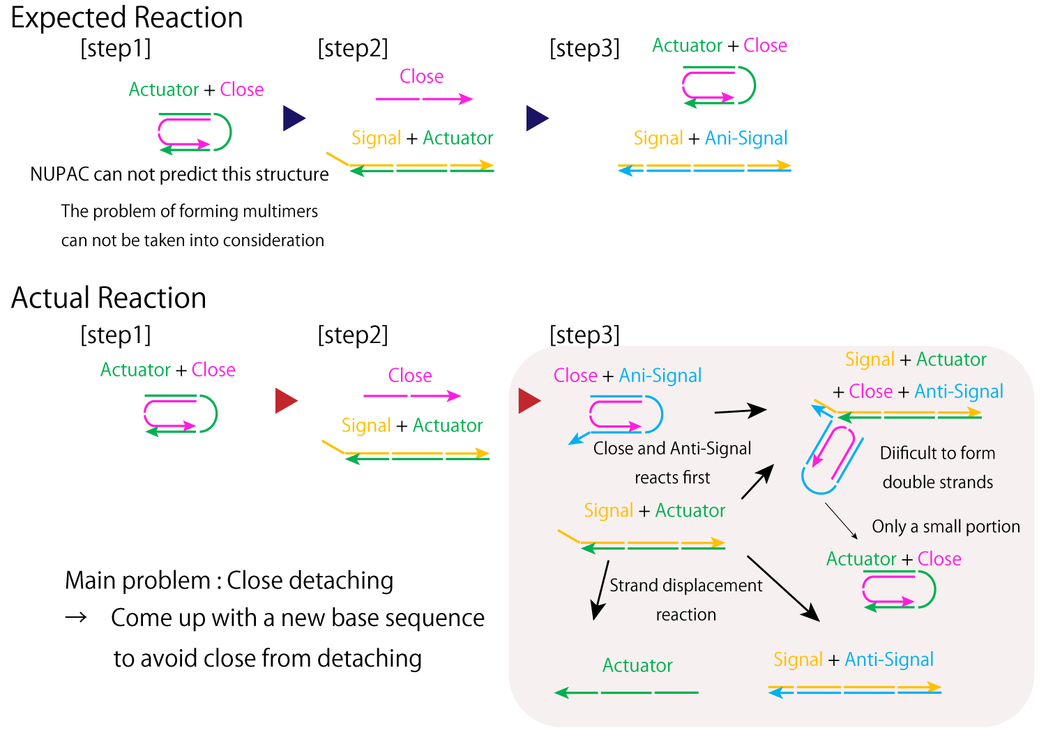
Fig.4 mechanism of designed DNA strands
Next, we compared Lanes 13 to 14 to see the optimal Anti-signal concentration, since no major changes could be seen between Lanes 14-19. Compared to Lane 14, in Lane 13, the band likewise to Lane 12, representing remaining hybridizations between Actuator and Signal was more clearly observed. Thus, we decided the optimal Anti-Signal condition to be that of Lane 14, where Actuator:Close:Signal: Anti-Signal was 1:1:1.2:2.
Miura Folding DNA Origami Unit Experiments
Here we aimed to fold the designed Miura-folding DNA Origami units by our designed strands.
Although ideally, alternative transitions between the closed and open states should be confirmed to see if the is design feasible, due to time constraints, here we decided to only confirm the closing of the units.
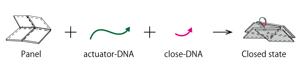
Fig.5 schematic of mechanism of actuator-DNA and close-DNA
3.3 Electrophoresis
Purpose
Here we added Actuator and Close to the DNA Origami panels to confirm the closing of our designed DNA Origami Units using Agarose gel electrophoresis.
Results and Discussion
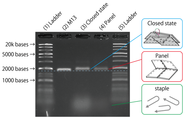
Fig.6 Electrophoresis of DNA Origami
From the results of gel electrophoresis shown in Fig. 6 , compared to Lane 2 with only M13, in Lanes 3 and 4, a band shift towards larger molecular weights could be observed, indicating the formation of larger structures. However, although it was hypothesised that adding Actuator and Close to close the Origami panels would change the structure and affect the mobility of the samples, from the bands alone, we were not able to see a clear difference between Lanes 3 and 4. Thus, we decided to further observe the formed structures using a different method.
3.4 AFM
Purpose
To further confirm the formation of our closed DNA Origami units, we observed the structures for the sample including Actuator and Close using AFM.
Results and Discussion
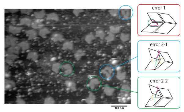
Fig.7 observation of DNA Origami with actuator-DNA and close-DNA by AFM
From Fig. 7, although we could observe multiple panel structures, we were not able to find a Miura Folding unit in its completely closed state. The results were assumed to be due to flaws in the sample preparation procedures. For the samples, since Actuator and Close were both added at the same time, the two may have hybridized together first before Actuator could properly be attached to the DNA Origami panels. Another possibility is that Actuator and Close interfered with the Hinge functions, perhaps by pulling in the panels too early and over-straining the Hinges connecting the DNA Origami panels, resulting in broken structures like those seen in Fig. A solution for this may be to avoid hybridization of Actuator and Close by applying Actuator during the annealing of the DNA panels.
4. Ideas for Improvement
Even from the limited experiments we were able to carry out, it could be told that there were flaws in the current design we had. However, if we modify the current strand sequences to improve the mechanism, it is thought to be in realizing Miura Folding of the DNA Origami units by only using single strand displacement reactions with Actuator. Below is the proposed improvised version of the design.
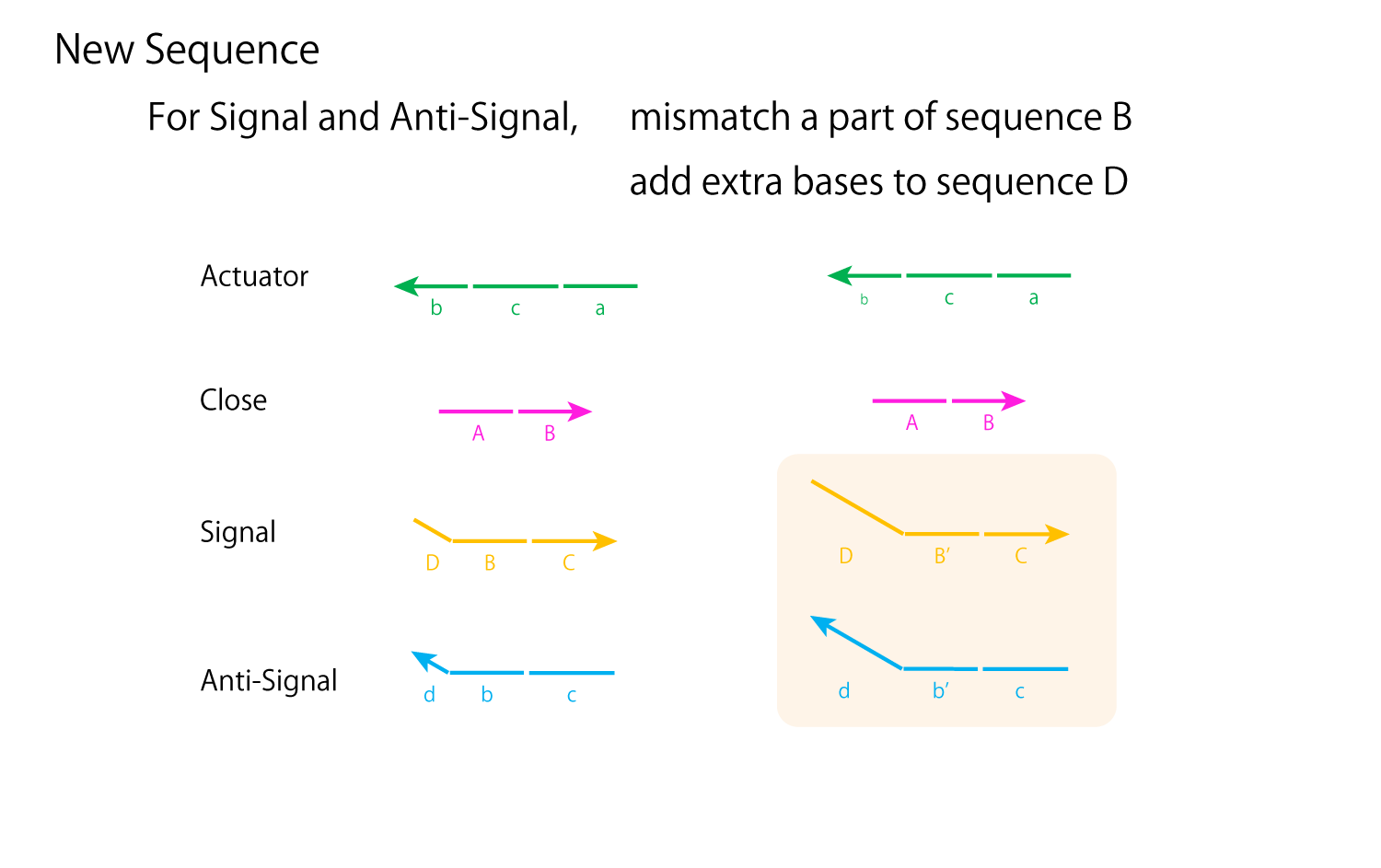
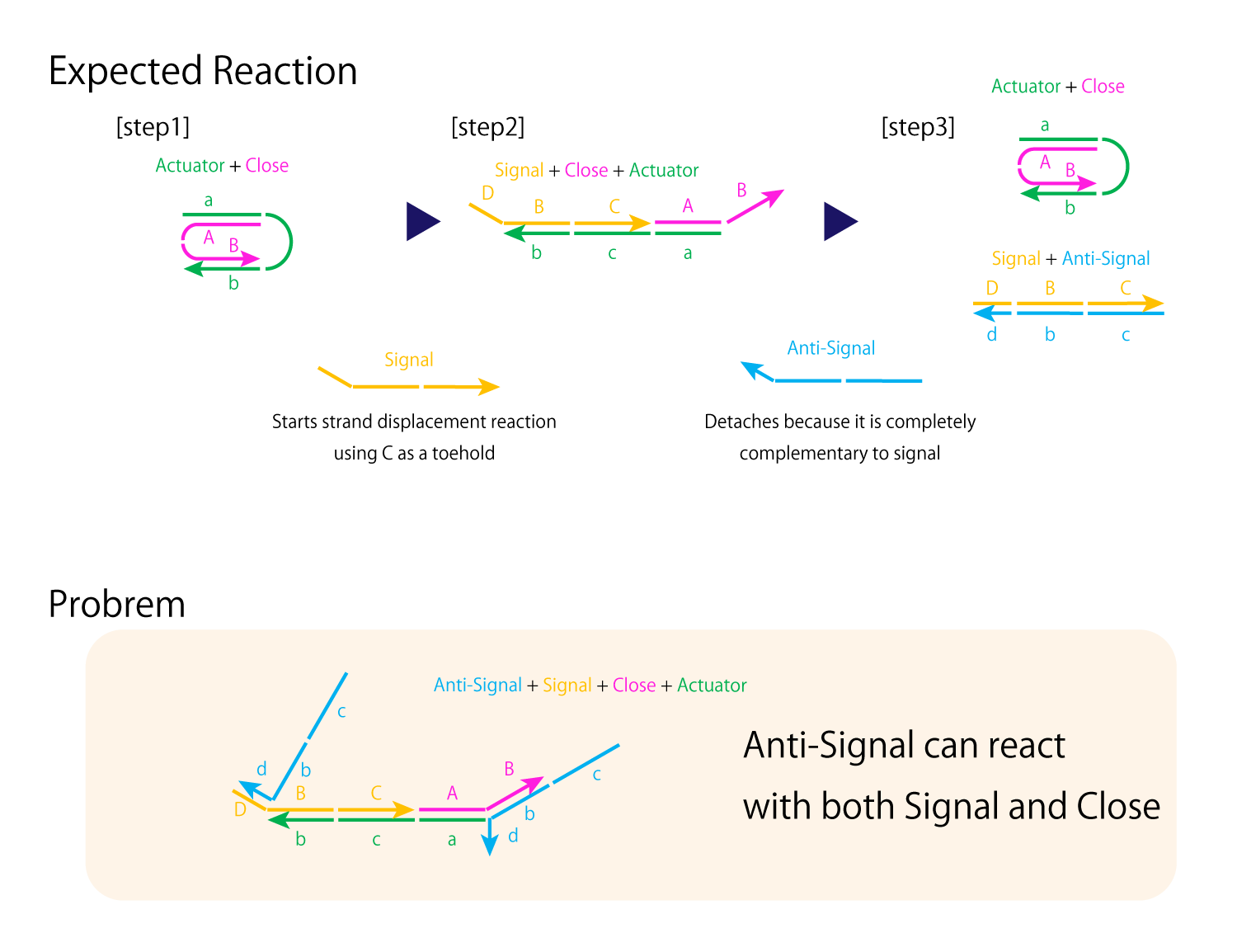
Fig.8 improvement of mechanism to close and open DNA Origami
From Experiment 3.2, the main problem of the open/close mechanism derives from Close and Anti-Signal hybridizing with each other, preventing proper hybridizations between Actuator and Close and forming unexpected multimers. In order to prevent Close from completely separating from Actuator, for the new design seen in Fig.8 , the DNA sequences of Signal and Close are shortened and strand displacement will occur using sequence c as a toehold. However, with this alone, Anti-Signal can still react with both Signal and Close. Thus, in order to assure Anti-Signal forms complete double strands with Signal, for only Anti-Signal and Signal, sequence B can be replaced with sequence B' which perhaps has 20% or so of its bases mismatched. Also, we can add extra bases to sequences D and d' of the two strands.
With this, proper strand displacement reactions can be realized, enabling the opening and closing of the DNA panels by Actuator.
Secondly, shape confirmation of designed DNA origami unit and its transformation after applying signal were achieved. As of the current design, however, it is geometrically difficult to fold the structure, due to the offsetted Hinge DNA strand arising from the rotation center of the inner vertices not passing through a single point.
Although at a glance these results seems to be contradictory, by analyzing the TEM image, at the site where the Hinge3 should exist, there is an open space around 6 nms, which is much over the length of the Hinge (1.32 nm) (Fig. 10, white arrow). From this, the Hinge3 is assumed to be stretched enough to fold a unit due to detached staple strands.
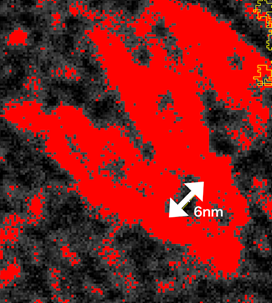
Fig.9 Analyzed TEM image for Closed unit
In order to confirm this hypothesis, the relation in distance between the vertices of the two parallelogram panels and the dihedral angles (Fig. 10) were plotted (Fig. 11). The red curve represents the simulation results for our origami unit with extended Hinge3 (Shown in fig.10. Hinge3) obtained by Unity (Movie 1), while the blue line represents properly foldable Miura Folding simulation (paper model) calculated by eq. 1. The scatter diagram shows the raw data values obtained from the TEM observations. When the value from the simulations are set as the expectation value, the raw data plots obtained from the TEM observations comparatively match the red graph: the model for the Miura Folding missing its Hinge3. In addition, error evaluation of the Chi-squared values for extended Hinge3 and Normal model (eq. 2) were calculated (70.69 and 282.57, respectively). The fact the calculated Hinge3 value is much lower than that of Normal indicates that our Closed origami unit with extended Hinge exists in higher possibility than as designed.
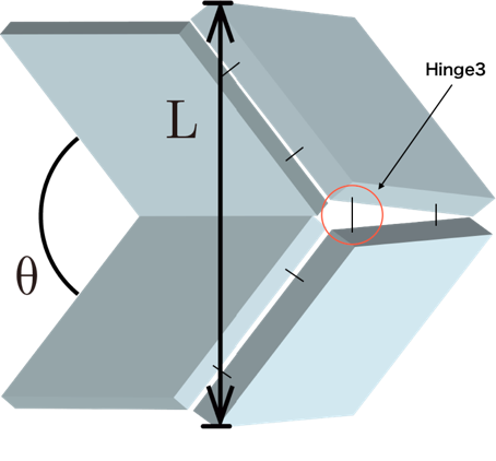
Fig.10 Model for analysis
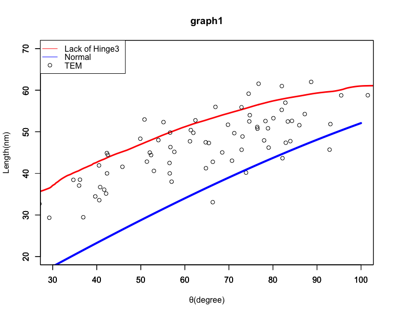
Fig.11 Analysis for comparing TEM and simulation results
Mov.1
\begin{equation} L = 2 ・34 ・ sin(\theta/2) \ \ \ \ \ eq. 1. \end{equation}
\begin{equation} Chi-squared \ value \end{equation} \begin{equation} \chi^2 = \sum\frac{(observed-expected)^2}{expected} \ \ \ \ \ eq.2. \end{equation} \begin{equation} Lack \ \ of \ \ Hinge3 \ \ : \ \ 70.69326 \end{equation} \begin{equation} Normal \ \ : \ \ 282.5725 \end{equation}
Although the lack of the hinge3 was an error, according to the simulation in Unity, this has no effect on the opening and closing mechanism, or rather, it enables a smoother transition between the two states (Movie 2).
s
However, the advantage of Miura Folding is not only that it enables dynamic open-close transformation, but also realizes coordinated movements when multiple units are connected. To realize coordinated movements, since the parallelograms constructing the Miura Folding units have to maintain their sides parallel, smooth motion can not be expected to be realized with incomplete Miura Folding. Because of the Hinge3 length is not equal to the others,this model is expected to be incomplete Miura Folding.
Even on the nanoscale level, in order to realize a Miura Folding with a certain degree of thickness like our designed structure, there is a need to resolve the above geometrical problems. Thus, we came up with a new design (Movie 2). In the newly proposed design, by offsetting the panels and trying to layout the Hinges on the same plane as much as possible, the geometrical problem can be resolved.
Mov.2
Since the sides of the parallelogram forming our new design of Miura folding origami unit are kept parallel, we assume that smooth and macroscale open-close transformation, such as multimeric origami complex as shown below, will be possible (Movie 3).
Mov.3