Experiment
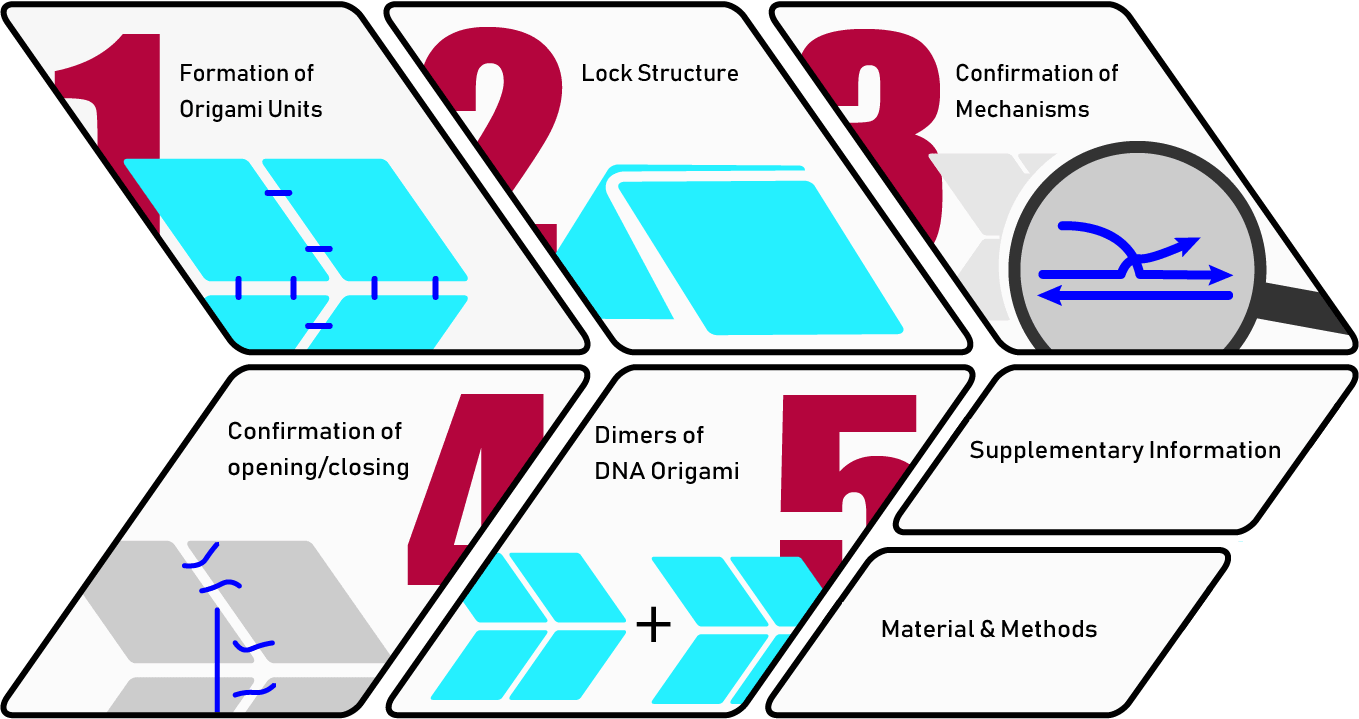
1. Formation of Origami Units
Purpose
By connecting DNA Origami panels with single-stranded DNA called Hinge, we aimed to realize minimum units to perform Miura Folding.
In this experiment, we confirmed if DNA Origami structures designed using caDNAno would form Miura Folding Units like the ones seen in the Cando simulations.
Results and Discussion
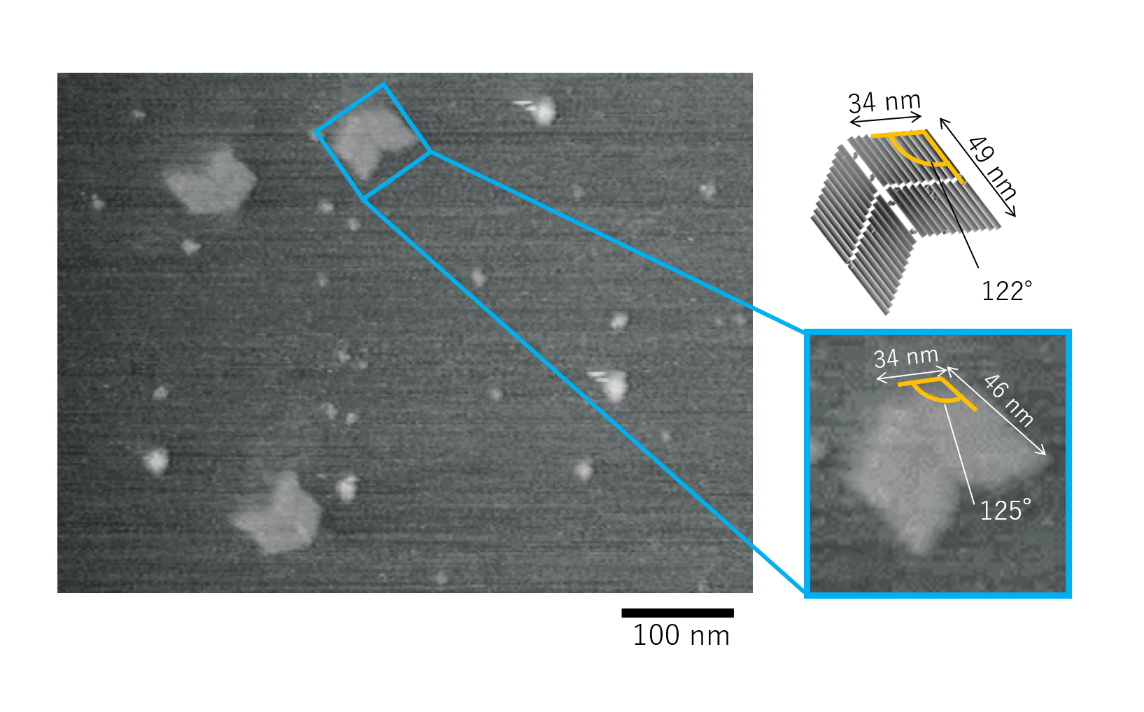
Fig.1 single Miura Folding units by AFM observation
From the figure, it can be seen that four DNA Origami panels form a single Miura Folding unit. Thus, it was confirmed that the DNA Origami and Hinge composing the Miura Folding unit were properly designed in caDNAno.
2. Lock Structure
Purpose
The goal of our BIOMOD project is to control the opening and closing of the Miura folding units made from DNA Origami. Thus, to contrast the observation results of the Miura Folding units in the closed state, we decided to form and observe pre-closed Miura Folding units. The units were pre-closed using "Lock" DNA strands which were attached in the same position as Latch.
Design
To observe the closed Origami structure, Lock DNA was designed to connect the sides of the panels.
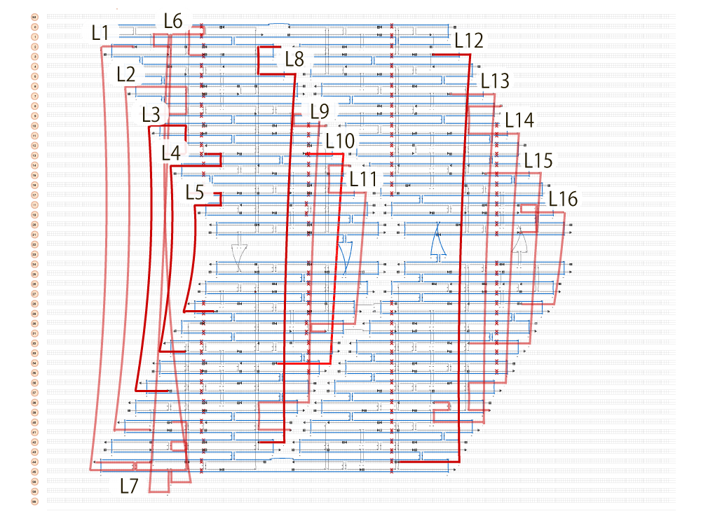
Fig.2 Lock DNA position designed by caDNAno
The red strands in the figure are the Lock DNAs designed using caDNAno. Lock DNA strands of N=1, 3, 4, 16 were inserted as shown in the figures below, and the annealed samples were observed using TEM.
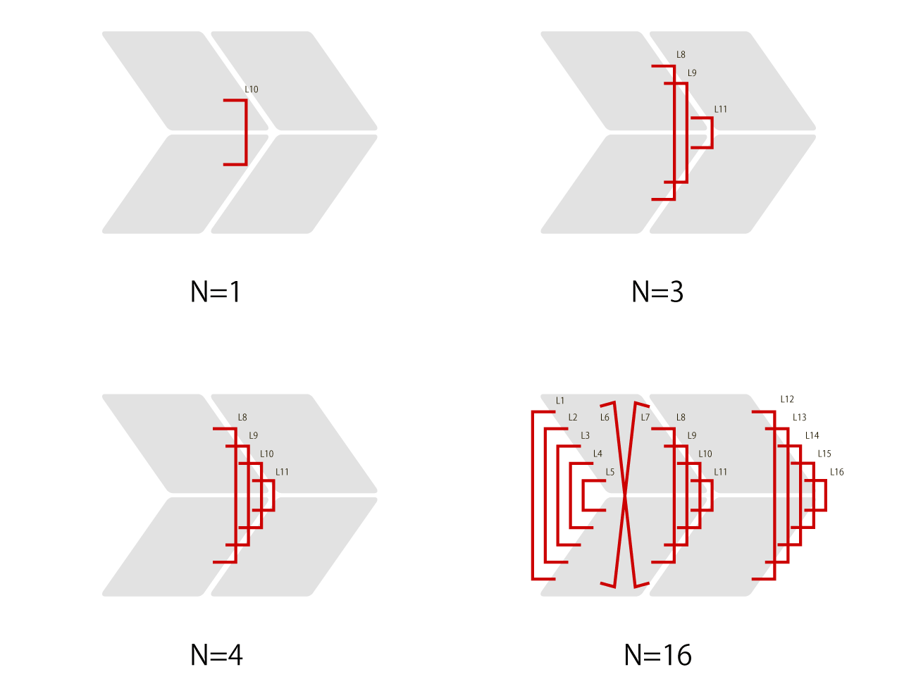
Fig.3 different amount of Lock DNA strands
Results and Discussion
In this experiment, in addition to observing the closing mechanism of the designed units, in order to see if the units are indeed the structures closed by Lock, the number of Lock DNA strands to close the designed units were changed to be 1, 3, 4, and 16, based on the preliminary experiments. (See Supplementary) The figure below shows the unit structures observed using TEM for N=1, 3, 4, 16 each.
N=1
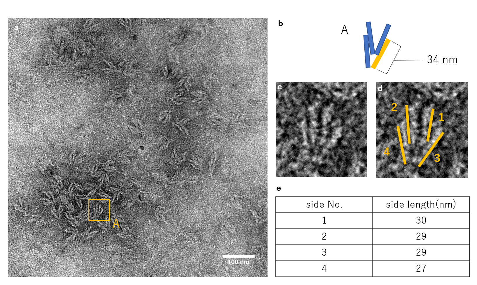
Fig.4_ (a)
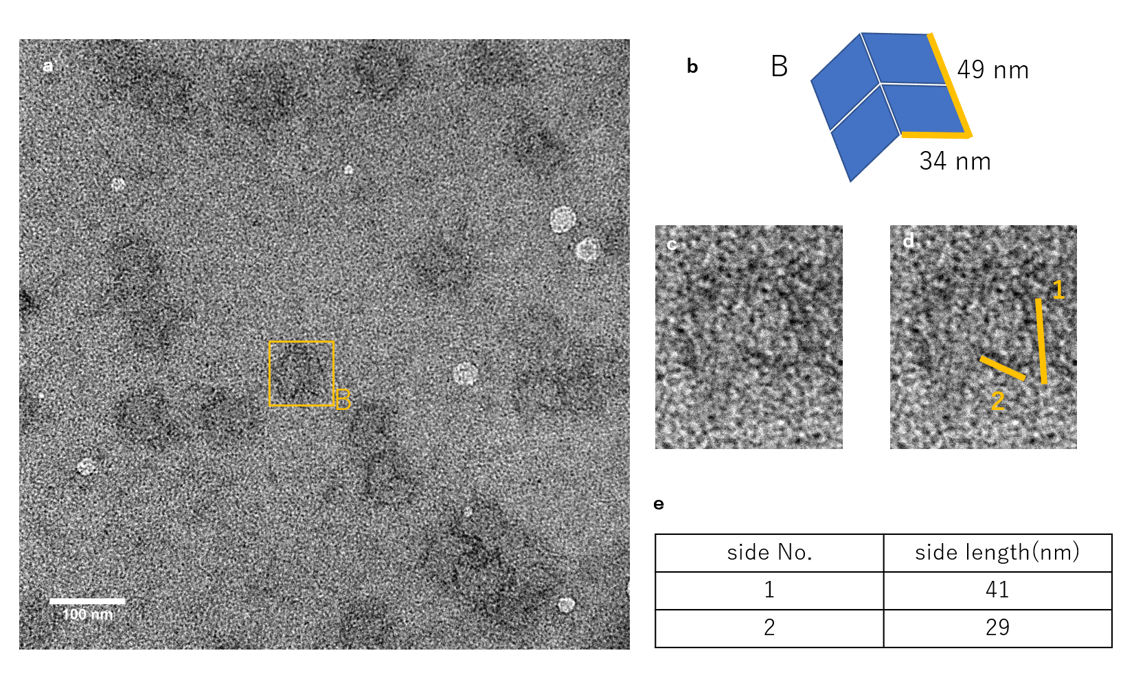
Fig.4_ (b)
The figure shows the TEM observation results for when a single Lock strand was inserted. A structure with a form similar to that of A, which is the closed unit seen from above, can be observed. Also, structures similar to B were observed as well.
N=3
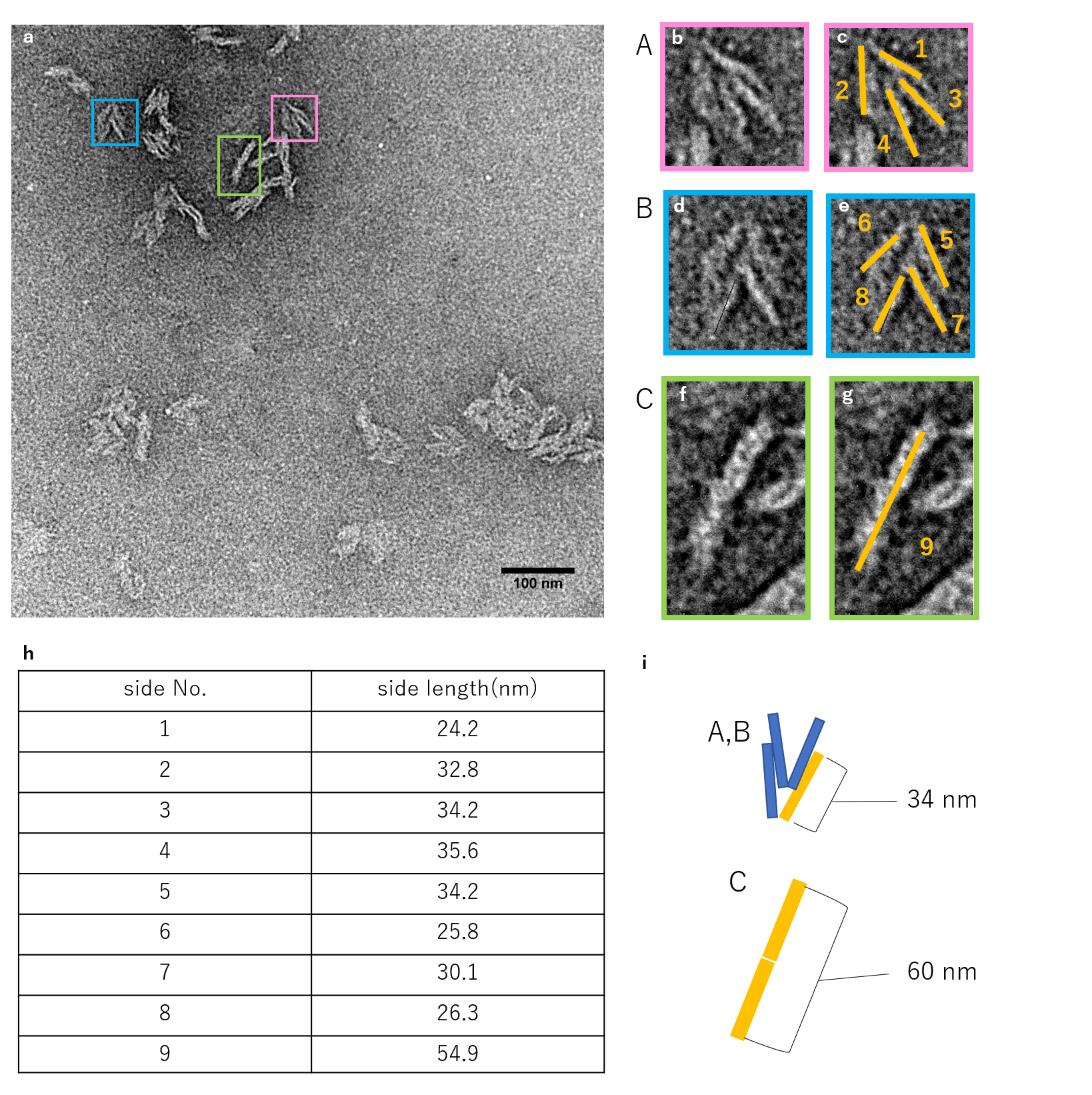
Fig.5 Observation of units closed by 3 Lock strands by TEM
The figure shows the TEM observation results for when 3 Lock strands were inserted. Multiple structures thought to be the closed units seen from above were observed (A), but at the same time, many structures not closed according to design (B) or opened structures (C) were also observed.
N=4
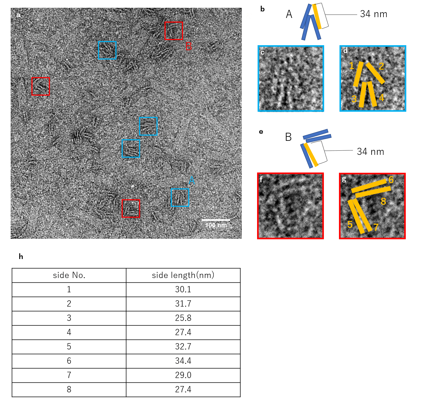
Fig.6 Observation of units closed by 4 Lock strand by TEM
The figure shows the TEM observation results for when 4 Lock strands were inserted. Occasionally, strands that were not completely closed like the one shown for N=3 were observed, but the majority showed to be the closed structures according to design.
N=16
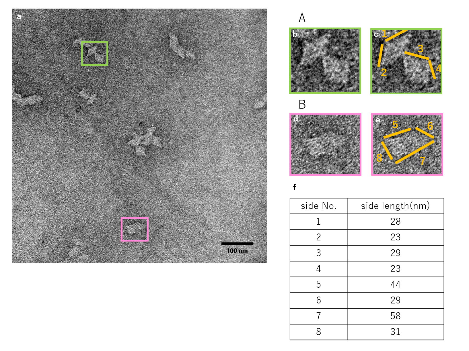
Fig.7 Observation of units closed by 16 Lock strands by TEM
The figure shows the TEM observation results for when 16 Lock strands were inserted.
In contrast to the results obtained for N=3, 4, structures closed according to design were not observed.
From these results, we were able to confirm that the designed structure could be folded as expected. In addition, based on the results, the number of Latch strands for each unit and their positions were decided to be the same condition as to when the number of inserted Lock strands was N=4.
3. Confirmation of DNA Strand Mechanisms
Purpose
From the previous experiments, formation of Miura Folding Units from DNA Origami and its closing mechanism according to design was confirmed. However, our goal is to realize a reconfigurable deployable DNA nanostructure which is both transformable and controllable. Therefore, we examined the mechanisms of Bridge and Latch DNA strands as well as the various strands needed for structure transformation using gel electrophoresis.
Results and Discussion
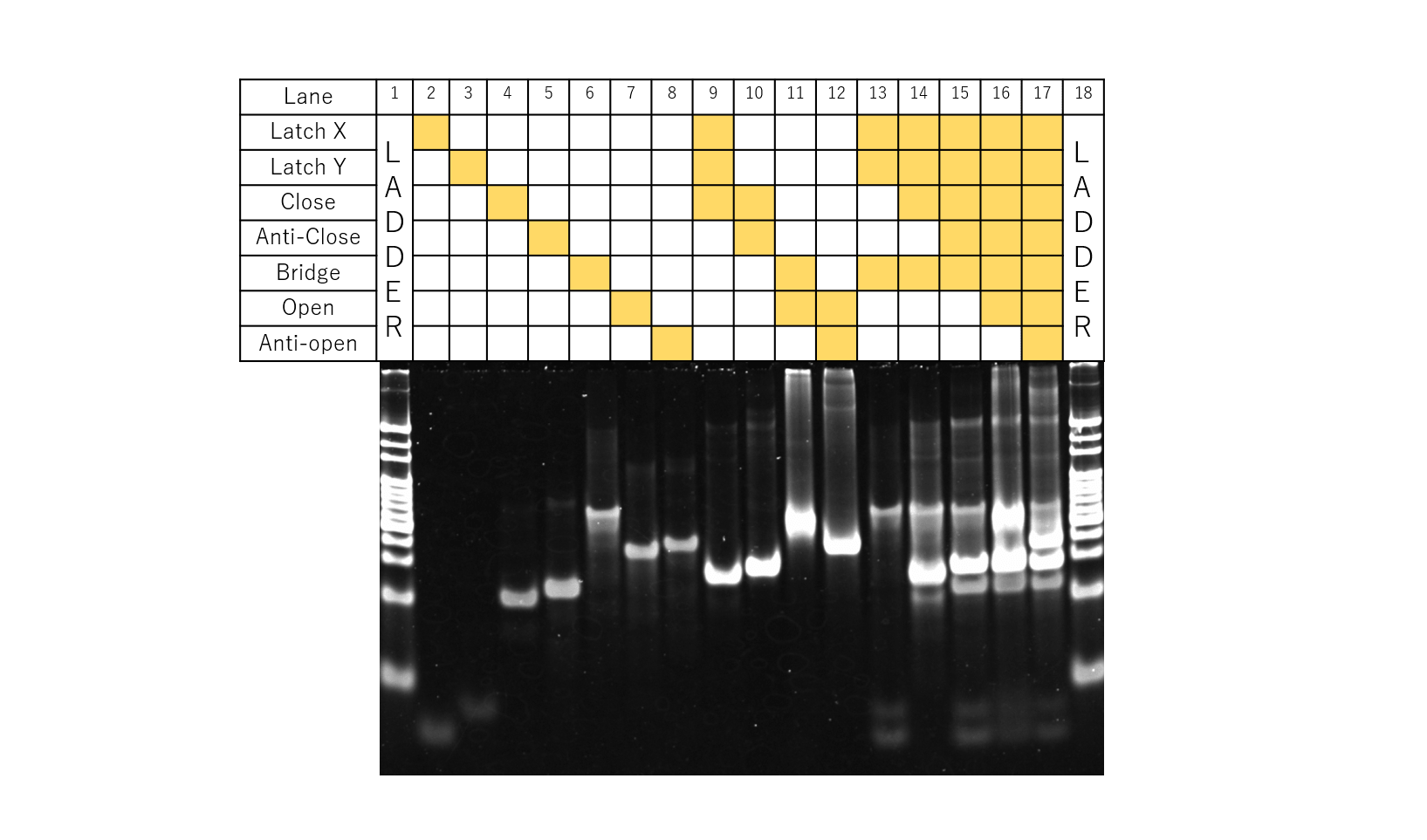
Fig.8 Electrophoresis for testing Latch X,Y, anti-close, bridge, open, anti-open
The above figure shows the gel electrophoresis results when each of the samples for Latch X,Y, Anti-close, Bridge, Open , Anti-open were prepared according to the table. First, from comparing Lanes 2, 3, 4, 9, in Lane 9, a band can be seen to exist in a different position from Lanes 2, 3, and 4. This can thought to be due to Latch X, Y and Close interacting with each other.
Likewise, the bands representing Close and Anti-Close n Lane 3, 4 were not observed in Lane 10, so the band observed in Lane 10 is thought to be obtained from Close and Anti-Close reacting with each other. Likewise, from comparing Lanes 6, 7, 8, 11, and 12, it can be confirmed that Bridge and Open, and Open and Anti-open react with each other.
Lanes 13 to 17 show the results for the sample where Latch X, Y and Bridge all exist simultaneously, while Close, Anti-Close, Open, and Anti-Open are applied in this order according to the open/close mechanism of the structure, taking the process needed for application to DNA Origamis into consideration.
Based on the results of Lanes 1-12, from the results of Lane 13, it can be told that both Latch types, Latch X, Y, and Bridge do not react together. Upon the addition of Close, as seen in Lane 14, the bands for Latch X, Y disappear. Thus, it was confirmed that Close reacts with both Latch X,Y even under conditions where Bridge exists in the solution. In addition, when Anti-Close was added to this, as seen in Lane 15, bands for Latch X,Y were once again observed, and bands identical to those of when Close and Anti-Close reacted were observed as well.Thus, Anti-Closed was confirmed to properly function. Likewise, for Lanes 16, 17, since similar results as Lanes 11, 12 were observed, Open and Anti-open were confirmed to function properly.
From these results, our designed mechanism can be expected to function properly even when attached to the DNA Origami.
4. Confirmation of Open/Close Mechanism of DNA Origami
Purpose
In the previous experiments, we confirmed our designed DNA strand mechanisms to be feasible. In order to further confirm the transformation mechanisms of the DNA Origami Units, we used TEM to observe the the transformation of the Miura-Folding Unit structures to different states according to our designed signals.
Results and Discussion
Purified samples of DNA strands along with the DNA Origamis, pre-confirmed by gel electrophoresis (Supplementary Experiment 4.), were diluted and observed by TEM. The results of the TEM observations for state ① Neutral, ② Closed, ③ Neutral, ④ Open are shown below.
① Neutral
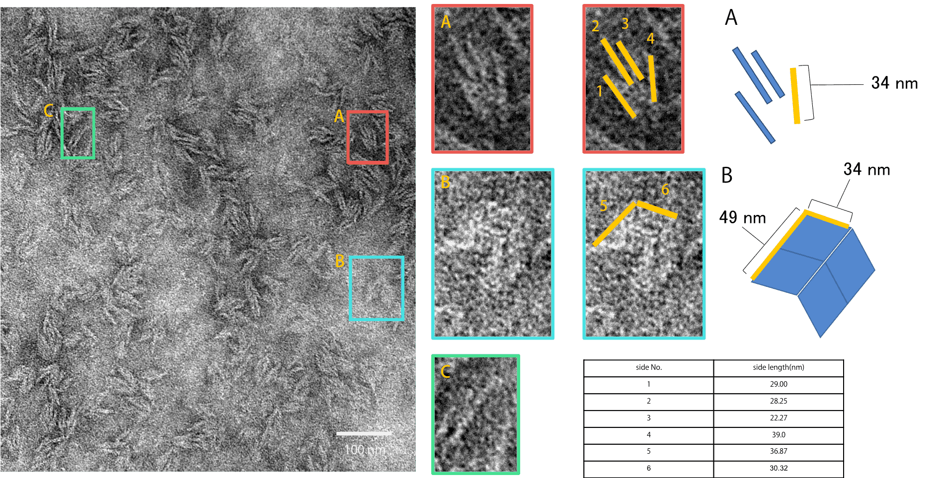
Fig.9 Neutral state_1
Fig. 9 is the TEM observation result of the Neutral state. As shown, closed structure A, open structure B, and a few unclassifiable structure C were observed. From the AFM observation result it was predicted to observe open structure B, but many of closed structure A were observed. Since the Origami units are gathered together closely in a flexible state, Origamis push each other and as a result close the units.
② Closed
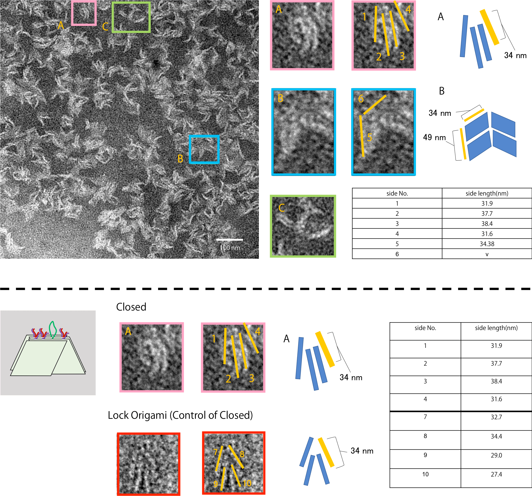
Fig.10 Closed state
Fig. 10 is the TEM observation result after adding Close strands into the sample. As shown, structures like A were observed. Since these structures have a similar shape as those after adding Lock strands in experiment 2, it can be said that the unit closed because of Closed strands. In addition, units that were open like B and unclassifiable structures like C were observed. However, most of the resultant structures observed had a bent shape like A or had a partially closed structure that were observed with lock number N = 4 in experiment 2. Thus, it can be concluded that the Close strand is ideally functioning.
/tem/tem_under-optimize.gif)
/tem/tem_upper-optimize.gif)
Video 1 Neutral to Closed
③ Neutral
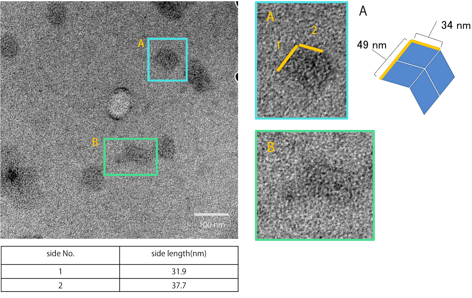
Fig.11 Neutral state_2
Fig. 11 is the TEM observation result after hybridizing Close and Anti-Close. In this sample, closed structures were not observed like in the initial sample of Neutral and Close. Thus, it can be said that Anti-Close strands functioned properly with the closed Origami panels.
④ Open
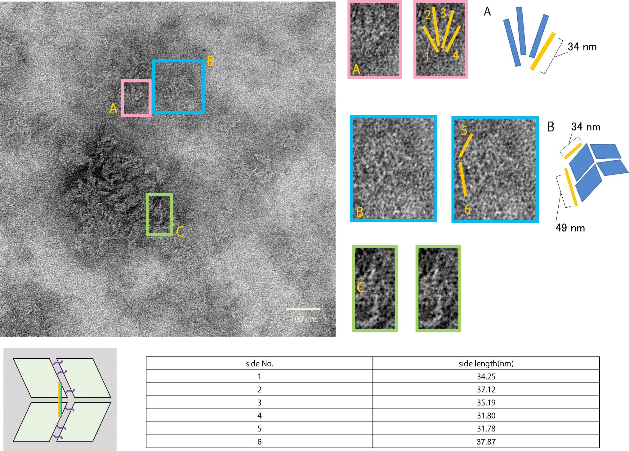
Fig.12 Open state
Fig. 12 is the TEM observation result of inserting Open strands into Neutral state Origamis (Fig. 11). As shown, closed structure A and open structure B were observed. Closed structures were not observed in Fig. 11, but were found in Fig. 12. Thus, Open strands are functioning properly and opened the unit.
5. Dimers of DNA Origami
Design
To realize dimers, single-stranded DNAs called “Linker” and two types of Origami units labeled unit_left and unit_right were designed. In the figure below, the green dotted lines represents where Linkers will attach. unit_left will attach Linkers on the right side of the unit, and unit_right will attach Linkers on the left side.

Fig.13 Sketch of mechanism of dimer DNA Origami
By connecting these two units Linkers, dimers are formed. In the figure below, the green straight lines represents the Linkers.
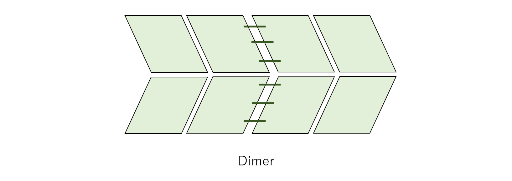
Fig.14 Sketch of dimer DNA Origami with linker
5.1 Confirmation of Dimer Formation by Gel Electrophoreisis
Purpose
In order to broaden the range of possible applications, our structure is designed so that multiple units can be connected to form larger structures and enable controllable transformation as a whole.
To confirm if multiple units can be connected according to design, here, we used multiple single-stranded "Linker" DNA to attach two Origami units together, forming dimers of our designed Miura-folding units. The results were observed using gel electrophoresis, and the optimum concentration of Linker was examined. In addition, further observations were made with TEM.
Results and Discussion
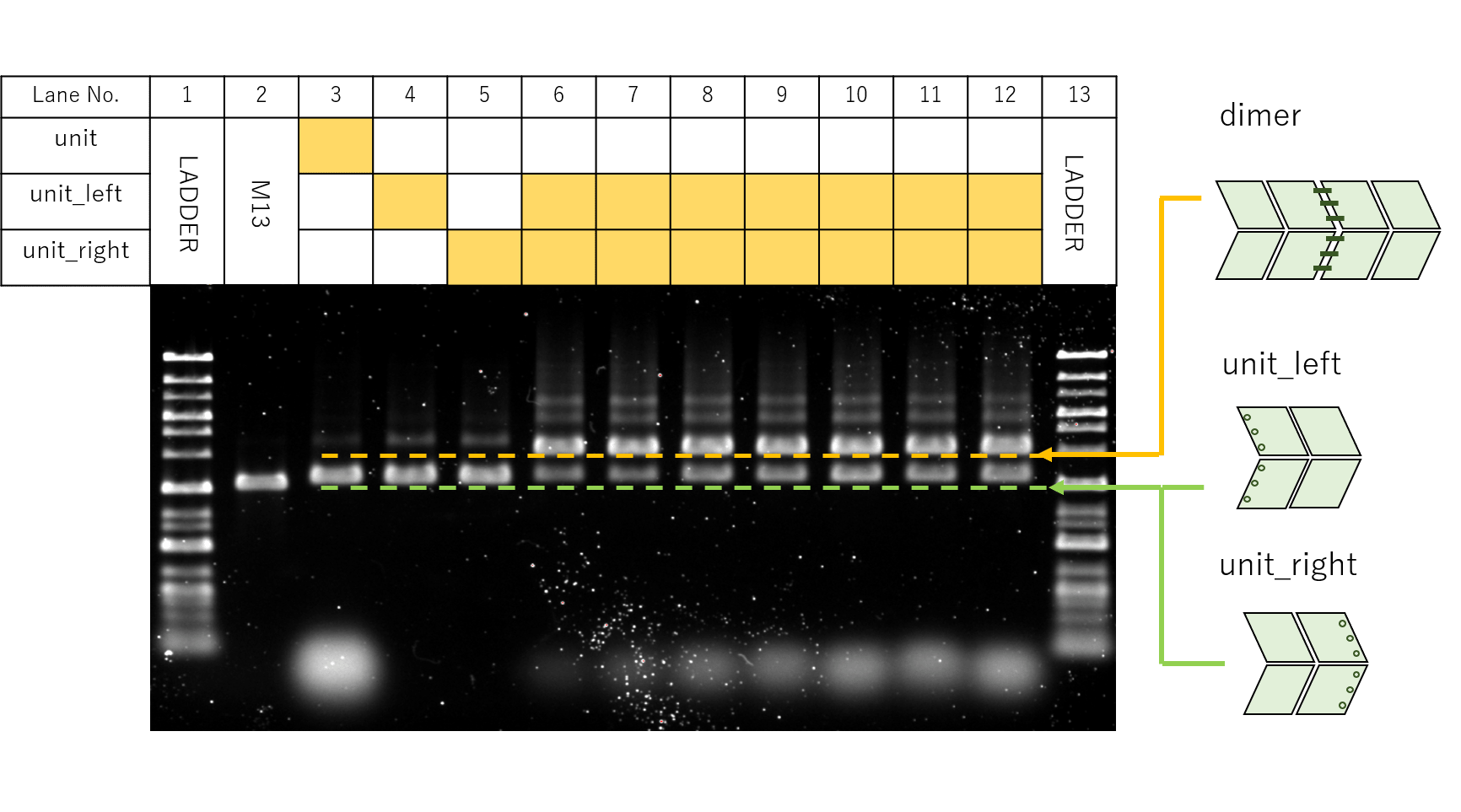
Fig.15 Electrophoresis of testing dimers annealed with different Linker soncentration
Fig.15 shows the gel electrophoresis results for the samples prepared according to the table. For Lane 4 and 5, monomers of Linker added units, unit_left and unit_right, were applied to each, while for Lanes 6 to 12, both left and right units were applied while the Linker concentrations were changed from 10 to 40 nM.
From Lanes 3 to 12, bands thought to represent monomers and dimers of our designed units were observed, while especially thick bands were seen for dimers in Lanes 6 to 12. For Lanes 6 to 12, smear-like bands were seen to stretch towards larger molecular weights along with increases in Linker concentrations, suggesting the formation of multimers of Linker-connected units.
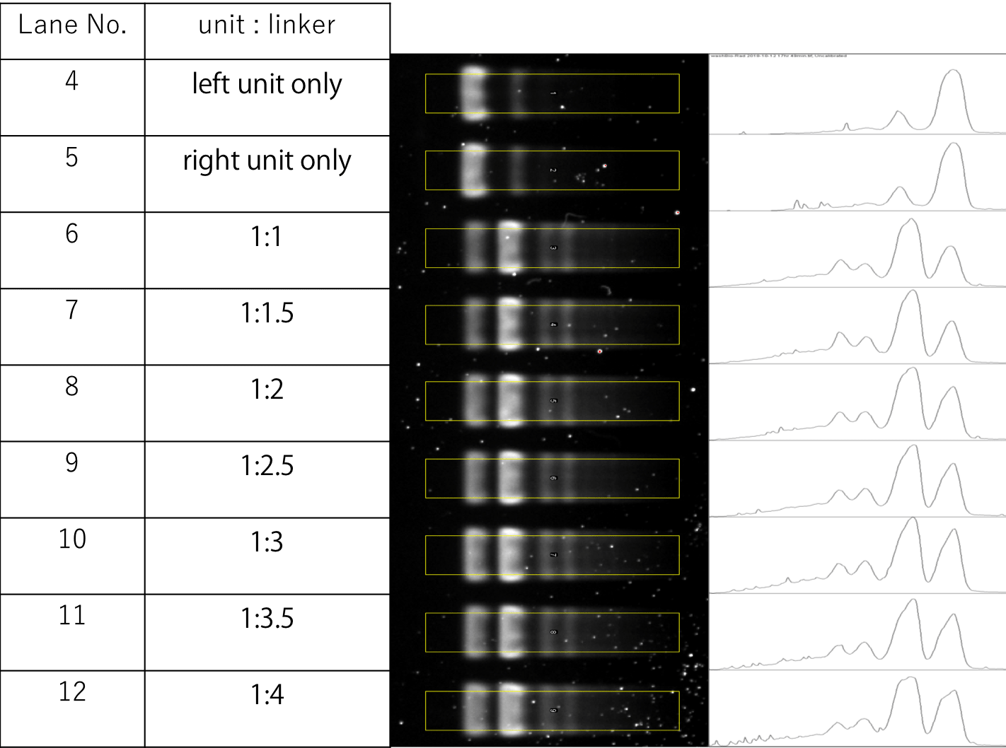
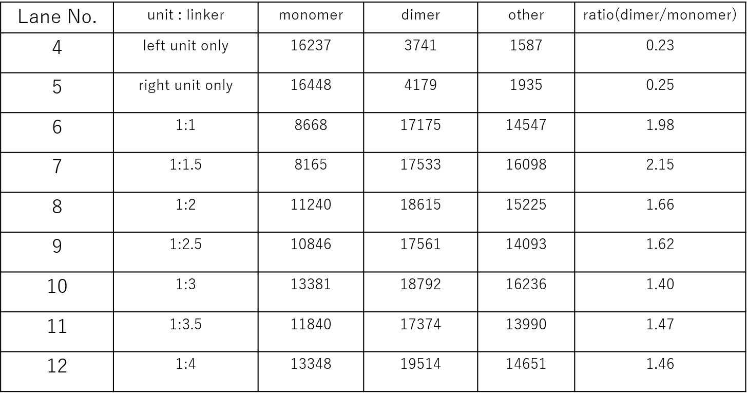
Further analysis was conducted by measuring the fluorescent intensity of the monomer and dimer bands of Lanes 4-12, and comparing their area in the graph to determine the dimer to monomer ratio. From the results shown in Fig.15 , it could be told that indeed Lanes 6 to 12 had higher dimer to monomer ratios compared to Lanes 4 and 5, and that Lane 7, with samples of unit:Linker ratios of 1:1.5, had the highest dimer to monomer ratio out of all. Thus, the samples for TEM were prepared according to the concentration condition of Lane 7.
5.2 Confirmation of Dimer Formation by TEM
Purpose
In the electrophoresis of 4.1, DNA Origami were confirmed to form dimers by adding Linkers. In this experiment, we will confirm if the dimers obtained in 5.1 form the expected structures according to design using TEM.
Results and Discussion
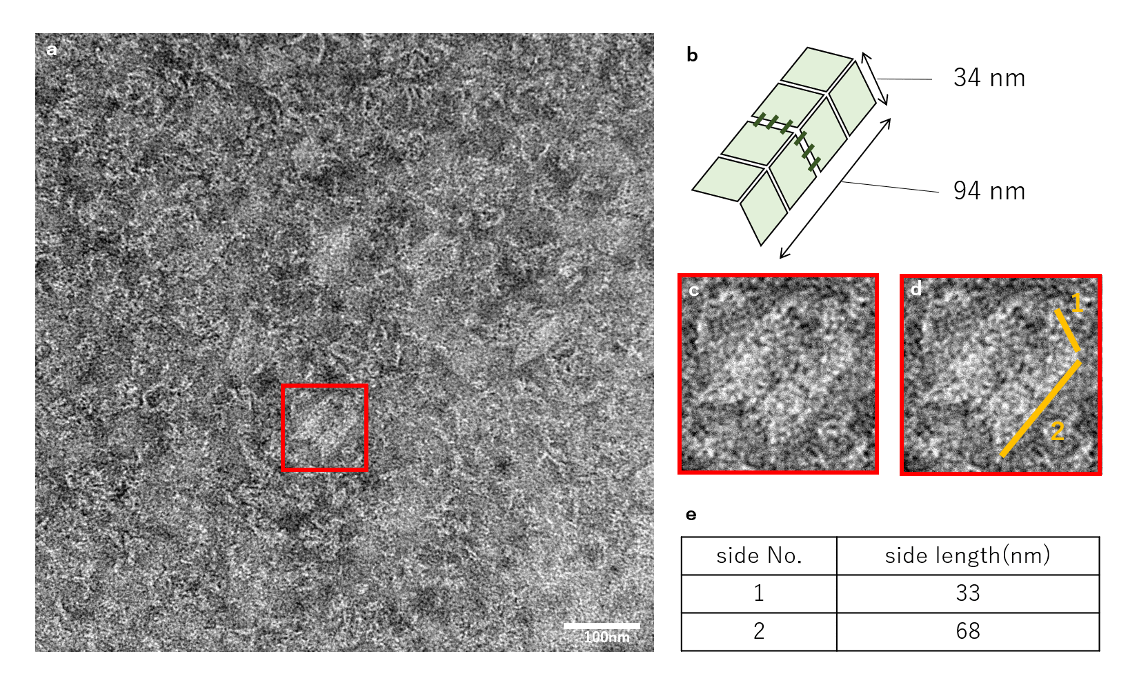
Fig.16 Dimer DNA Origami combined by Linker by TEM
The TEM results for samples of Unit:Linker concentrations of 1:1.5 are shown in Fig. 16. Structures thought to be Miura Folding Unit dimers were observed, and the yield of dimer was 10.2%. In addition, as seen in Fig.16, several units showed trimer or multimer formations.
With this, the formation of large structures of multiple units was confirmed. By connecting these designed units, a large DNA nanostructure performing Miura Folding can be expected to be formed in addition to gaining controllability by adding signals.